|
Home Page | Products | Contact Us | News & Events | Request Info. |
||||
|
|
Technical Information |
|
||
|
|
||||
|
|
Please contact us for information on the following subjects:
Individual Optical
Fibre Bend Radius
Optical Fibre
Acceptance Angle
|
|||||||||||||||||||||||||||||||||||||||||||||||||||||||||||
|
Back to top | Home Page | Products | Contact Us | News & Events | Request Info. |
|
|
|
|
|
|
|
|
Copyright © 2007 Glen Spectra All rights reserved |
|


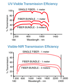
 The
graphs to the right show the transmission characteristics for fibre
optic bundles and single fibre cables. The curves for the bundles
have included in the transmission the losses due to packing factor,
reflections at the entrance and exit, and the losses within the fibre
itself. Please contact us if you need a more detailed explanation or
to discuss your requirements.